Sunday, August 24, 2008

Converting Old Dos Drawings

On thing that concerns (or should concern) long term users of C&G surveying software is the ability to use older versions of drawings, coordinate files, point groups and raw data files. There is good news for those concerned about accessibility of older files.

For the past several versions C&G has included the ability to convert the old PL files to dwg files. The process is really easy and fairly quick. Before I show you how the process works, I do want to issue a word of warning. When you convert a PL file, a new dwg will be created with that same name. If you previously had a dwg file with the same name as the original PL file, it will be over written without warning. Be careful when converting these old drawings. You can find yourself losing data when the existing file is over written.

With that warning, let me show you how to convert the old PL files.

Begin by starting the program.

There are two basic steps. First, we must Setup the process. During this setup we define the data path for CG Inserts. CG Inserts from the PL file will converted to CAD Blocks.

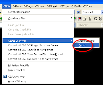
Go to the CGFile pull down menu. Choose CGFile>CGDos Drawings>Setup.

Figure 1.

When the CG Dos Drawing conversion Box opens, set the data path for any CG Inserts referenced in the PL file you wish to convert. In this case, the Inserts for our drawing are contained in data path c:\data\95060.

Figure 2.
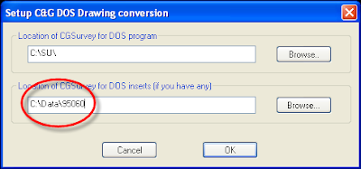

When the data path is properly set, Choose OK.

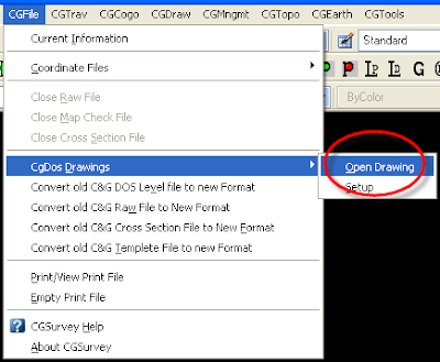
Next we go back to the CGFile pull down menu. Choose CGFile>CGDos Drawings>Open Drawings.

Figure 3.

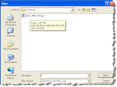
Next we choose the drawing we wish to open.

Figure 4.
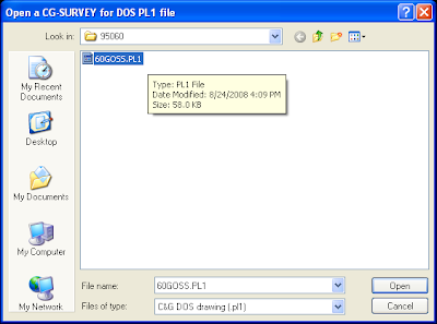

After chosing the file and then Open, the process begins. The time necessary to complete the conversion will vary with the size of the drawing being converted. Simple drawings happen in a few seconds. More complex drawings will take a bit longer. (Even very large drawings should take less than a minute to convert.)

The the drawing layers being converted will show in the command line.

Once complete, the conversion successful dialog box will appear. Note the warning. I always encourage everyone to keep their color and pen width definitions consistant. Doing so will insure your old drawings will look the same as your new drawings and vice versa.

Figure 5.
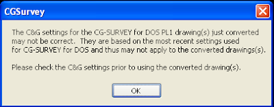

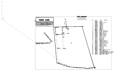
Figure 6 shows the converted drawing. This particular drawing is a realitively simple preliminary drawing. The conversion not perfect. I sometimes have issues converting my title block. This is partly because I used attributes in my DOS drawings.

Also you'll find drawings containing "J" line types won't look the same when converted. (A CG Dos J line type is a double line offset from the center.) These do not convert properly to CAD because until recently AutoCAD did not support double offset lines.

Figure 6.


Larry P
Saturday, August 16, 2008

Draw Mapcheck and Input Scale Factor

I want to touch on a couple of topics with this post. One is a way to take a deed description written in units other than feet (or meters). The other function I want to highlight is new to CG Survey 9. The Draw Mapcheck function.

Let's start with a deed written in poles. (One pole equal 16.5 feet). Figure 1 shows a fairly typical Mapcheck file from my records.

Figure 1.


Notice the distance units I have in the Mapcheck file. The first deed distance is 10 poles. Insert each distance just as it appears in the deed.


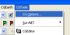
Close the Mapcheck file and go to the CG Tools> CG Options Pull down menu. (Figure 2.)

Figure 2.


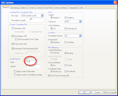
In the CG Options Dialog box you will find the Scale Factor Options in the lower left.

Figure 3.


Since we know 1 pole = 16.5 we change the Input Scale Factor to 16.5. Close the CG Options Dialog box by choosing the OK button at the bottom. (If you close the dialog box by clicking the red x in the upper right your changes will not be saved.)

Next let's take a look at the Draw Mapcheck function.

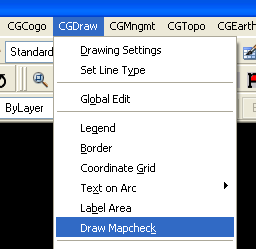
Go to the CG Draw > Draw Mapcheck function.

Figure 4.


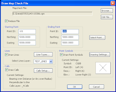
The Draw Mapcheck dialog box allows us to do many things. At the top of the box you see we have to choose exactly which Mapcheck file we wish to work with. If needed, we can even edit the file by choosing the Edit File button.


Figure 5.


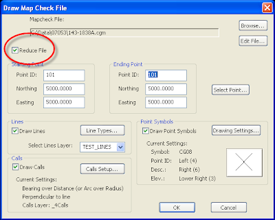
We have control of all the elements of a map. We can reduce the Mapcheck file to coordinates. We choose the starting and ending point numbers as well as coordinates for those points. See Figure 6.


Figure 6.


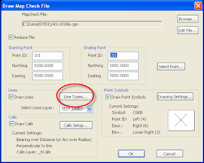
We can change the line type to be used. See Figure 7. If the line type you wish to use is not a part of the current drawing you can even add the type from a linetype file. See this post and this post for more details on linetype files.

Figure 7.


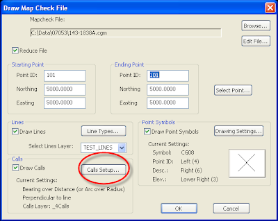
If we wish to draw calls on our map we can use the Calls Setup button to set them as we wish. See Figure 8.

Figure 8.


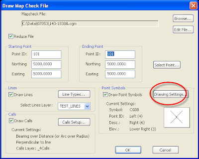
You change the point symbol and annotation settings by choosing the Drawing Settings button. See Figure 9.


Figure 9.


Once we have all our options set, choose the OK button. Your map is drawn and annotated per your choices. See Figure 10.

Figure 10.


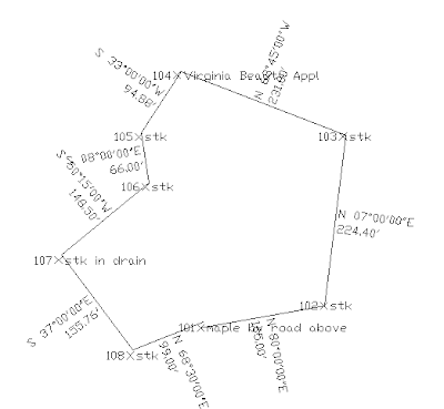
Certainly this quick sketch is not ready to hand to a client; but, it does show you can quickly get data on the sheet. Minor moving of calls or point descriptions are easy at that point. Also note that our distances are shown in feet. The magic of the Input Scale Factor has converted the distances for us.

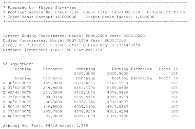
Finally, if we look at the reduced data we see the closure report and that the coordinates are correctly calculated in feet. See Figure 11.

Figure 11.


Larry P

Friday, August 8, 2008

Converting Raw Data Files to CGR

I had a call this week from a friend having some problems converting a TDS data collector file to a cgr file he could edit with his C&G Raw Data Editor.

I was able to help and thought it might make a good post for others. So, here is how you convert non-CG type files to CGR files.

First, you'll need to download the raw file to your hard drive. (Be sure you make note of the location of the file on your hard drive.)

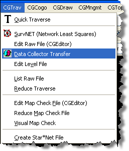
Once the file is on your hard drive Open C&G and go to the CGTrav pull down. Select Data Collector Transfer.

Figure 1.


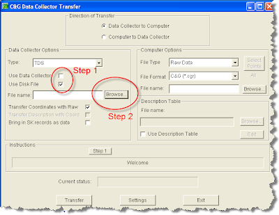
Next set the Data Collector Type file to match the raw data type you have. Remember the type is not the hardware type. It is the software type. In this case I was converting a TDS type file.

Figure 2.

Since you have the raw data file on your hard drive already, you need check the Use Disk File option. Then you click Browse. This will allow you to designate which file you want to convert.

Figure 3.

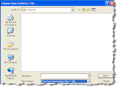
Usually when you get to the folder containing the file you wish to convert, you won't see the file listed. This is because C&G is looking for a file extension that may not match the actual extension of your file. If this happens, go to the bottom of the screen and change the Files of type button.

Figure 4.


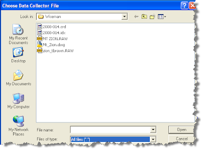
You want to show All Files (*.*)

Figure 5.


If you have the correct folder you should see the file you wish to convert. Choose it now. In this case I wish to convert zion_tbrown.raw so I choose it.

Figure 6.


This will return you to the Data Collector Transfer box. Next we set the File Format on the Computer Options side of the CG Data Collector Transfer box. We set the File Format to C&G(*.cgr)

Once you have the File Format set you are ready to choose Transfer

Figure 7.


The transfer happens really quickly. Once done, the CG Transfer Report dialog box will pop up. This box allows you to choose the location and file name for the new file.

Figure 8.


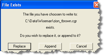
If you choose a location and file that already exist, you have the option to replace or append the existing file.

Figure 9.

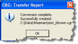
After taking care of these options you should receive a Conversion complete notice.

Figure 10.


If you wish to confirm the conversion Use the CG Editor to Open the file.


Figure 11.

You now have a cgr file ready to edit or ready to investigate using the Raw Data Graphic Viewer.

Larry P